Thursday, December 16, 2010

Basics of data transfer & Network Cabling

Transmission and Network Cabling

Cables play vital role in networking domain. A medium of data transmission from one point to another point.

Types of CABLES, CONVERTERS

Co-axial Cable:

what consists inside a coaxial cable? There is a little copper conductor which is surrounded by one white insulator, and then there is another conductor. There is different type of metal and aluminum foil for second conductor. And all are wrapped with polyvinyl chloride or plastic jacket. It is called coax because those two conductors, the one copper in the middle, and the big metal sheathing around that, both of those conductors share the same center point so as they have same axis and called co-axial. 

There are different types of coaxial cable they can be called as RG (Radio Grade) type and there are many RG rating cables such as RG-58, RG-59, RG-6, RG-11, etc. All these co-axial cables come with connectors known as RF connector. All the connectors differ by its inner diameter of the outer conductor and as 3. 5mm, 2. 4mm, 1.85mm and 1 mm. Presently co-axial cables were being used at Modems and TV Cables. 


Twisted pair cable:

It is called twisted pair cable because it is always in pairs and each pair is twisted around itself. The twisting allows the signal to propagate further down a piece of copper wire. Twisted pair cabling was originally invented back in early 1970s for telephone systems and twisted pair cabling has become the most common form of cabling in networking domain. 

The twisted pair cable is available in two variants i.e. Shielded, Unshielded twisted pair cable. And one of the big improvements that we see with unshielded twisted pair is its ability to work with faster and faster networks.

CAT Cable (Unshielded Twisted Pair or UTP) 

A standard UTP cable consists of 100-ohm copper cable made with 2-1800 unshielded twisted pairs protected by an outer jacket. It is used for LAN networks. 

Depending on the certain speed and bandwidth of networks, the unshielded twisted pair cables were categorized or rated as Category and called as CAT 1, CAT 2, CAT 3, CAT 6, CAT 7 etc. The older telephone cable, we had used, has a Cat rating called Cat 1. So these different cat numbers have different speeds for data transmission. But in case of Cat 7 cable it is originally shielded twisted pair cable. Each individual pair has its own customized shielding around it, to separate one from another. 


Cables are standardized by EIA/TIA [National Industry Association/ Telecommunication Industry Association] and NEC [National Electrical code] like wise:

1.Copper
2.Copper covered steel.
3.copper covered other.

Basically UTP cables are used for ethernet with RJ 45 connector. These cable are used for the computer networking. Its a 100 ohm copper cable consisting up to 1500+ (1800) unshielded twisted pairing. It have no metallic shield still, its not protected from the electrical interference.   

Capacity Of Data transfer at the cables -

  • CAT1: up to 1 Mb/s for voice communication only, traditional telephone connection
  • CAT2: Up to 4 Mb/s used for token ring networks.
  • CAT3: 10Mb/s used for ethernet connectivity
  • CAT4: up to 16 Mb/s used for token ring networks.
  • CAT5: 100Mb/s used for ethernet and can support up to 100 meters of connectivity capacity. 
  • CAT5e: up to 1 Gb/s used for ethernet, fast ethernet and gigabit ethernet.
  • CAT6: up to 10Gb/s used for gigabit ethernet and 10G ethernet and up to 55 mtr capacity 
  • CAT6a: up to 10Gb/s used for gigabit ethernet and 10G ethernet and up to 55 mtr capacity 
  • CAT7: up to 10Gb/s used for gigabit ethernet and 10G ethernet and up to 55 mtr capacity 


RJ45 connector/Plug
RJ 45 pin Description:-

  Pin No.||       Description ||
       1             Tx (+)
       2             Tx (-)
       3             Rx (+)
       4             Not Use
       5             Not Use
       6             Rx (-)
       7             Not Use
       8             Not Use.


                                                          UTP cable cat-6

#The UTP cable is crimped in to RJ45 by its colour code.
#The patch cord used to form two types according to compatibility of communication by using colour codes: Straight through and cross over.


NB: For Same Device type Cross over cable used.
       For different type device Straight through cable is used.

Colour Code For Straight and Cross cable

RJ45 modular plug

 
RJ-45 Crimping tool

UTP-6 Keystone jack or Plug
Standard Rj colour code
Standard patch cord for LAN connectivity
 
Key points to remember:
  • Same Device [Connected by Cross over]
  • Different Device [Connected by Straight through]

Fiber Optic Cable / Optical Fibre Cable (OFC):-

The optical fiber cable contains the fiber optics to carry out signal. The signal or data communication is basically due to the LED [Light emitting Diode] or Laser.
It uses multiplexing technology which maximizes the capacity of transmission .
Different types of OFC are used as: multi core, multi mode and single mode.
 
The Single-mode cable is designed to be used with lasers. It has a much thinner piece of fibre inside it and the cladding is tighter. It can transmit longer distances.
 
We have to note one important thing that multimode is almost always orange, and single mode is always yellow in colour. 

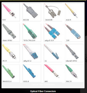
Similarly there are different types of connectors for Ofc is being used such as ST, SC, FC, LC, MT-RJ, etc.


Single mode

Multimode-multicore/outdoor use only


Different types of ofc  (Optical Fibre Cable) Connectors.

OFC cable SPLICING .

 
CABLE SPLICING machine.
splicing machine


SPLICING of cable is needed when there a joining comes. It is to join regular  and buried in the ground or may be inside Distribution Box. It is needed to join two short cables to one cable for communication. Hence there are two types of Splicing i.e. 1.Mechanical 2.Fusion Splicing.

1.Mechanical Splicing is done by mechanically, holding two ends together and wrapped inside a  joint.
2.Fusion Splicing is done by two fiber cores are welded or fused together by heat, but it costs higher.

After Splicing of the OFC Cable  it is being tested by OTDR Machine for signal strength and loss status.

OTDR 


TYPICAL DISTRIBUTION BOX


OTDR: Optical Time-Domain Reflecto meter

It is an Opto-electronics device used to detect any problems on the fibre links. To check the health of the signal communication through fibre.

--------------------------------------------------------
CABLE (DB9-RJ45):- 

Basically used for Configuration of Routers and Switches we use CONSOLE CABLE ( DB9 to RJ45).


standard console cable

CABLE X.21 (DB60-DB15):- 

This cable is used for Cisco access servers access pro cards and for higher family of routers i.e. 7000,4000,3600 etc. used for connecting devices.


fig: standard DB60-DB15 cable


Ethernet to fiber converter:-

The Media Converter complies with IEEE 802.3z, IEEE 802.3AB Standards. It is designed to convert data signal between 10/100Base-T and 100Base-FX Fast Ethernet. It supports 10/100Base-T and 100Base-FX applications. The Converter is equipped with 2 single fiber optic connectors (One for transmitting-TX and another for receiving-RX) and one RJ-45 Jack and one external power supply receptacle. Six LED indicators are built-in for easy diagnosing and monitoring the status of power, Unshielded Twisted Paired (UTP) Link, UTP Activity, Fiber Link, Fiber Activity, Full duplex and data rates. It can be configured automatically for Full Duplex or Half Duplex operation.

SFP Module:
The small form factor pluggable (SFP) is a network interface module used for both communication of data and voice. It comes for SFP port of Routers and Switches.

It comes with different speeds such as Fast Ethernet to Gib Ethernet. 

Type of connectivity:- 

RJ45 SFP Module with Cat6 Cable, Fibre SFP Module with Fibre optic cable.

It links the router and switch in a network. Modern switches are designed to have two or more SFP modules in built

One sample module is illustrated as below;


In case of Cables, sometime all the lying cables should be managed well or should be kept in structured way to avoid any interference in signal and data. Before installation of cables, they should be measured well. 

In Data Centre or large networks sometimes cable management is a complex task. It can be Horizontal cable management, vertical cable management, Patch panel, cable tray system, various clamps, tags etc.


-DR

Tuesday, December 14, 2010

Basics of Storage and Memory

Basics of Storage and Memory

Disks and Memory 

We all have known the memory sizes of storage devices such as SDCARD, USB drive, HDD, SSD, RAM in terms of Mbps, Gbps very easily. But What is the smallest size and bigger size in case of memory, lets have a look below;

A computer uses a binary number system called a Bit. Its either 0 or 1. Means a single bit is 0 or 1.

So, 8 Bits = 1 Byte

Which means 8 binary digit is called 1 byte. A byte is a unit which is used to represent a character such as letter, number and symbol. It is a string of bits. 

Now so as,
  • 1 Kb (Kilobyte) = 1024 bytes (b)
  • 1Mb (Megabyte) = 1024 Kilobytes (Kb)
  • 1 Gb (Gigabyte) = 1024 Megabyte (Mb)
  • 1 TB (Terabyte) = 1024 Gigabyte (Gb)
  • 1 Pb (Petabyte) = 1024 Terabyte (Tb)
  • 1 Exabyte (Eb) = 1024 Petabyte (Pb)
  • 1 Zettabyte (Zb) = 1024 Exabyte (Eb)
  • 1 Yottabyte (Yb) = 1024 Zettabyte (Zb)
HDD: (Hard Disk Drive)

A hard disk is a electro-mechanical storage device used for storing data (image, audio, video, document etc.) in a magnetized medium. It comes with various sizes such as 40GB, 60GB, 500GB, 1TB and more. Used in computers and servers.
They have several interfaces such as PATA (Parallel ATA), SATA (Serial ATA).
Data being stored in the HDD in form of logical blocks on the rotating platters.

SSD: (Solid State Drive)

Here is uses electronics circuits integrated to store the data through non volatile flash memory (NAND Flash chip). This is significantly faster than the HDD.

Below is the comparison between the SSD and HDD for reference.


Buffer:

Buffer is a temporary memory that hold or reserves data for some time for access. 

Cache memory:

Similarly cache memory is one type of fast memory acts as buffer between RAM and CPU of a system. It enables the fast retrieval of data. They are differentiated in three levels such as L1, L2 and L3 and size ranging from 8KB to 64KB. The largest L3 ranges from 4MB to 50MB.

For Server end or Data Centre end, we basically use storage system to keep all the data stored as well as backed up. storage is a technology consisting of computer components and recording media that are used to store digital data. 

In case there we are using RAID configuration for the Storages.

RAID is known as Redundant Array of Inexpensive (or Independent) Disks and is combined of multiple physical disk drive components into one or more logical units for the purpose of data redundancy and performance improvement.
  • Array of multiple small, independent hard disk drives that yields performance exceeding that of a Single Large Expensive Disk (SLED).
  • A RAID disk subsystem improves I/O performance on a server using only a single drive.
  • The RAID array appears to the host server as a single storage unit.
  • I/O is expedited because several disks can be accessed simultaneously.
  • RAID can be managed in the software by the OS or in hardware by RAID controller.
The RAID architecture is based on configuration of RAID. Type of RAID is provided below;
  • RAID 0: Data Striping
  • RAID 1: Mirror / Duplex
  • RAID 5: Stripe set with distributed parity
  • RAID 6:     Double Parity.
  • RAID 10: Combination of RAID 1 & RAID 0
  • RAID 50: Combination of RAID 5 & RAID 0
RAID 0

RAID 0 is also known as stripping. It provides high data throughput and specially for large files. It does not provides fault tolerance or better redundancy. So in case of any drive fails, all data will be lost.

RAID 1

RAID 1 known as Mirroring, As data is to a drive, RAID 1 copies identical data to a second drive at the same time. Mirroring offers excellent data protection and delivers good performance when a mirrored drive fails. RAID 1 reduces the maximum drive capacity by half.

RAID 2

RAID 2 uses bit-level striping and each sequential bit is placed on a different hard drive with Hamming code Parity. However it is not so popular for using.

Parity Info:

Parity is a common way of detecting errors in a storage system. This is a way of adding checksums into data that can detect errors during data transmission. The way parity works is by adding a single bit of data to the end of a data block to ensure that the number of bits in the block is even or odd.


RAID 5

With RAID 5, each entire data block is written on a data disk and parity information is striped across all drives. It is most popular RAID level as it delivers data protection and good performance with a small overhead for parity. 

RAID 50

RAID 50 is combination of RAID 5 & RAID 0, Data is striped over RAID 5 sets.  It Can sustain loss of more than one disk as long as they are not in same configuration as of RAID 5. 


-DR

Basic networking definitions

Common Networking Definitions


1. Network Infrastructure

Set of physical and logical components that allow for among the features, security, management and connectivity.

2. Physical infrastructure 

Physical infrastructure is also known as network's topology, the physical layout of hardware components and the type of hardware as well as the technology used with hardware for data transmission.

3. Logical infrastructure 

Logical Infrastructure is the software that allows for communication over physical infrastructure, it includes services that run on the network like DNS.

4. Network connection  

Network Connection is a logical interface between software and hardware layers.

5Network protocol  

Network Protocol is the language used for communication between networked computers.

6Workgroup 

Workgroup is a simple grouping of resources which by default uses NetBIOS naming system. NetBIOS is used together with Common Internet File System (CIFS), an extension of Server Message Block (SMB) protocol, to provide file sharing. There is no centralized security in a workgroup environment. The default workgroup name is WORKGROUP. In the absence of a WINS server the NetBIOS names are resolved using broadcasts to local network segment.

7Domain 

A Domain  is a collection of computers that share a common directory, security policies and relationships with other domains. The name 'domain' is used both by grouping of computers in AD [ Active Directory] and as names in DNS, they are different things.

8AD 

Active directory is a distributed database that provides directory service.
9Subnet mask 

A subnet mask is used in a network to determine whatever the packet is destined for the current network or not. It does that by masking the network part of the IP address. The PC proceeds by finding his own network address using his IP and subnet mask in a bitwise AND operation. Then the PC does a bitwise AND operation on the destination IP and his subnet mask to determine foreign network address. If the addresses match then the packet is to travel on the local network, if the don't then the packet is destined to a foreign address.

10Default gateway 

Default Gateway is the IP address of a routing device [ i.e. a Router]  that accepts packets destined to other networks. Other networks are subnets that are not within the broadcast range of the PC that contacts default gateway (itself it is within broadcast range).

11. Encapsulation: 

The process of enclosing data in a packet is known as encapsulation.


-DR

Thursday, May 27, 2010

Basics of STM & SDH

STM

Basically refers as Synchronous Transport Module. Sometimes we hear it or tell it as STM card, used at Router end for connectivity with ISP.

STM-1: 

STM1 is a synchronous digital hierarchy (SDH) is standardized multiplexing protocols that transfer multiple digital bit streams over optical fiber using lasers or light emitting diodes (LEDs).

The STM -1 is the basic transmission format for SDH. Module level 1 is the SDH ITU-T fiber optic network transmission standard. It is one type of Electrical optical Converter [OC 3] . 

  • It has the transmission bit rate of 155.52 Mbits.
  • STM-1 operates in 1.31 micrometer lasers for 40km over single mode and 1.55 for longer.
first stm-1 generator


STM-1 card used for router


The STM-1E card has three card-level LED indicators. 

The red FAIL LED indicates a hardware problem on the STM-1E card; the green ACTV LED indicates that the STM-1E card is active and ready to carry traffic. The yellow SF LED indicates a problem receiving incoming data (loss of signal [LOS], loss of frame [LOF], or high bit error rate [BER]) on one or more of the STM-1E ports on the card.

STM-1 Frame:

The basic STM-1 carrier frame is made of 8 overheads, 4 pointers and a space for the payload. The overheads are the Regeneration Section Overhead (RSOH), linked with the regenerators, and the Multiplex Section Overhead (MSOH), associated with the multiplexers.

Regenerator Section Overhead (RSOH):

The Regenerator Section Overhead uses the initial 3 rows and 9 columns of the STM-1 frame. It monitors the network sections that present on the fiber-optic cable network.

Multiplex Section Overhead (MSOH):

The Multiplex Section Overhead uses the rows 5 to 9 and the first 9 columns of the STM-1 frame. It contains the information that allows data packets to be transmitted on the same network related to other data packets.

Both overheads deliver information on the transmission system and its management function, such as failure detection, service channels and transmission quality monitoring.

Like wise STM 1 there are other variants of SDH transmission rates as STM-4, STM-16 and STM-64. Sometimes combinedly we call it as STM-1/4/16 SDH Multiplexer.

Below are the transmission bit rate,
STM-4 = 622.080 Mbit/s
STM-16 = 2,488.320 Mbit/s or approx. 2.5 Gbit/s
STM-64 = 9,953.280 Mbit/s or we can say approx. 10 Gbit/s

SDH 
Synchronous Digital Hierarchy

Synchronous Optical Networking [SONET] or Synchronous Digital Hierarchy are a standard for data transmission or we can say, it is a standardized multiplexing protocols that transfer multiple digital bit streams over optical fiber using lasers or Light Emitting Diodes.

  • It is a transport Protocol.
  • The STM-1 frame is basic transmission format for SDH. 

The STM-1 frame is transmitted in exactly 125ms therefore 8000 frames per second on Fiber Optic ckt.

PDH

Plesiochronous digital hierarchy or PDH was used earlier in network for data transmission through microwave or fibre optical cables. Later PDH has been replaced by SDH.

-DR

Friday, March 26, 2010

Basics of E1/T1 Link

Basics of E1/T1 Link or Data rate

E1:

It is the Basic Data rate of communication in telecommunication. It is the lowest level of the Plesiochronous Digital Hierarchy (PDH) and is among the most common ways of transmitting voice & data over telephone and data networks. Physically E1 is transmitted as 32 timeslots.

STANDARDS OF E 

E0=64 kbits/second
E1=2.048 kbits/s
E2=8.448 Mbits/s
E3=34.368 Mbits/s
E4=139.264 Mbits/s
E5=564.992 Mbits/s

E1 Link
  • E1 link operates over two separate sets of wires. Usually Twisted pair cables.
  • A nominal 3volt peak signal is encoded with pulses using a method that avoids long periods without polarity changes.
  • This is an ideal for voice telephone calls where the voice is sampled.
  • The line data rate of E1 is 2.048 Mbits/S. full duplex [2.048 Mbits/s upstream and downstream] which is split in to 32 time slots each being allocated 8 bits in turn.
  • So each time slot sends and receives an 8bits/s of sample.
  • 8000 times per second = 8* 8000* 32 = 2,048,000.
  • The timeslots are numbered from 0-31.
  • One timeslot ( TS0 ) is reserved for framing purposes and alternately transmits a fixed pattern.

TS0= Synchronization, Alarm transport, international carrier use.
E1 has 30 circuits.

One timeslot [ TS16] is often reserved for signalling purpose to control call setup and teardown according to telecommunication protocol.

This includes channel associating Signaling ( CAS ) where a set of bits is used opening and closing the ckt. where CAS is known as per trunk signaling , a form of digital communication.

PHYSICAL E1
Here two types of physical delivery option are available for E1:
  • UNBALANCED [120w]: COPPER WIRE 4 [ One pair for TX ( 4+5) one pair for RX ( 1+2)
  • BALANCED [75w]: COAX with BNC connector [one cable for RX and one cable for TX]
E1 Frame

The E1 framing is the first level in the digital hierarchy. The E1 frame carries 30 voice channels in a 256-bit frame. Since 30 channels only require 240 bits; 16 bits are available for framing, signaling, error checking and supervisory communications. These extra 16 bits are divided into two groups of 8 bits each.

E3 Frame

A group of E1 circuits bundled on to higher capacity E3 links between telephone exchanges or countries. This allows a network operator to provide a end-to-end E1 circuit between customers in different countries that share single high capacity links between them.
  • E3 has 480 circuits.
  • E3 has 512 timeslots and data rate as 34.368 Mbits/s.


-DR

Monday, March 22, 2010

Basics of PSTN

PSTN 
PUBLIC SWITCHED TELEPHONE NETWORK


PSTN is the global collection of interconnects originally designed to support circuit-switched voice communication. The PSTN provides the traditional Plain Old Telephone Service (POTS) to residences and many other establishments. Parts of the PSTN are also utilized for DSL, VoIP and other Internet-based network technologies.

The basic PSTN network link supports 64 Kbps bandwidth. In residences, the PSTN phone line caring this bandwidth is typically a copper cable. Traditional dial-up modems utilize nearly 56 Kbps of this bandwidth when connected to a phone line. The PSTN utilizes the SS7 signaling protocol.

Transfer of information in the PSTN takes place over land lined trunked lines consisting of fiber optic cables, copper cables, microwave link and satellite link. 

-DR

Wednesday, March 10, 2010

Basics of Radio (RF)

Radio frequency (RF) 

RF radiation is a subset of electromagnetic radiation with a wavelength of 100km to 1mm, which is a frequency of 3 KHz to 300 GHz, respectively.

This range of electromagnetic radiation constitutes the radio spectrum and corresponds to the frequency of alternating current electrical signals used to produce and detect radio waves.

RF can refer to electromagnetic oscillations in either electrical circuits or
radiation through air and space. Like other subsets of electromagnetic radiation, RF travels at the speed of light.

In order to receive radio signals, for instance from AM/FM radio stations, a radio antenna must be used. However, since the antenna will pick up thousands of radio signals at a time, a radio tuner is necessary to tune in to a particular frequency (or frequency range). This is typically done via a resonator (in its simplest form, a circuit with a capacitor and an inductor).

The resonator is configured to resonate at a particular frequency (or frequency band), thus amplifying sine waves at that radio frequency, while ignoring other sine waves. Usually, either the inductor or the capacitor of the resonator is adjustable, allowing the user to change the frequency at which it resonates.


Electrical currents that oscillate at RF have special properties not shared by direct current signals. One such property is the ease with which they can ionize air to create a conductive path through air.

This property is exploited by 'high frequency' units used in electric arc welding, although strictly speaking these machines do not typically employ frequencies within the HF band. Another special property is an electromagnetic force that drives the RF current to the surface of conductors, known as the skin effect.

Another property is the ability to appear to flow through paths that contain insulating material, like the dielectric insulator of a capacitor.

The degree of effect of these properties depends on the frequency of the signals.

-DR


Network Scanning Tools

Network Scanning through Nmap and Nessus Network scanning is a process used to troubleshoot active devices on a network for vulnerabilities....